A multimeter is a measuring instrument that can measure multiple electrical properties. A typical multimeter can measure voltage, resistance, and current, in which case can be used as a voltmeter, ohmmeter, and ammeter. Some feature the measurement of additional properties such as temperature and capacitance.
Source: Wikipedia
Our group is using a DT-830D WellHise multimeter.
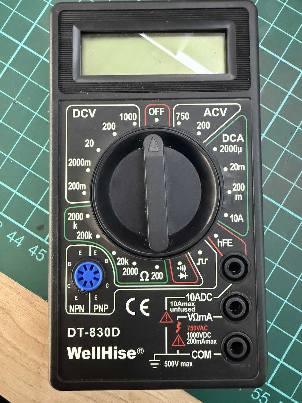
Multimeter: Link
Parts:
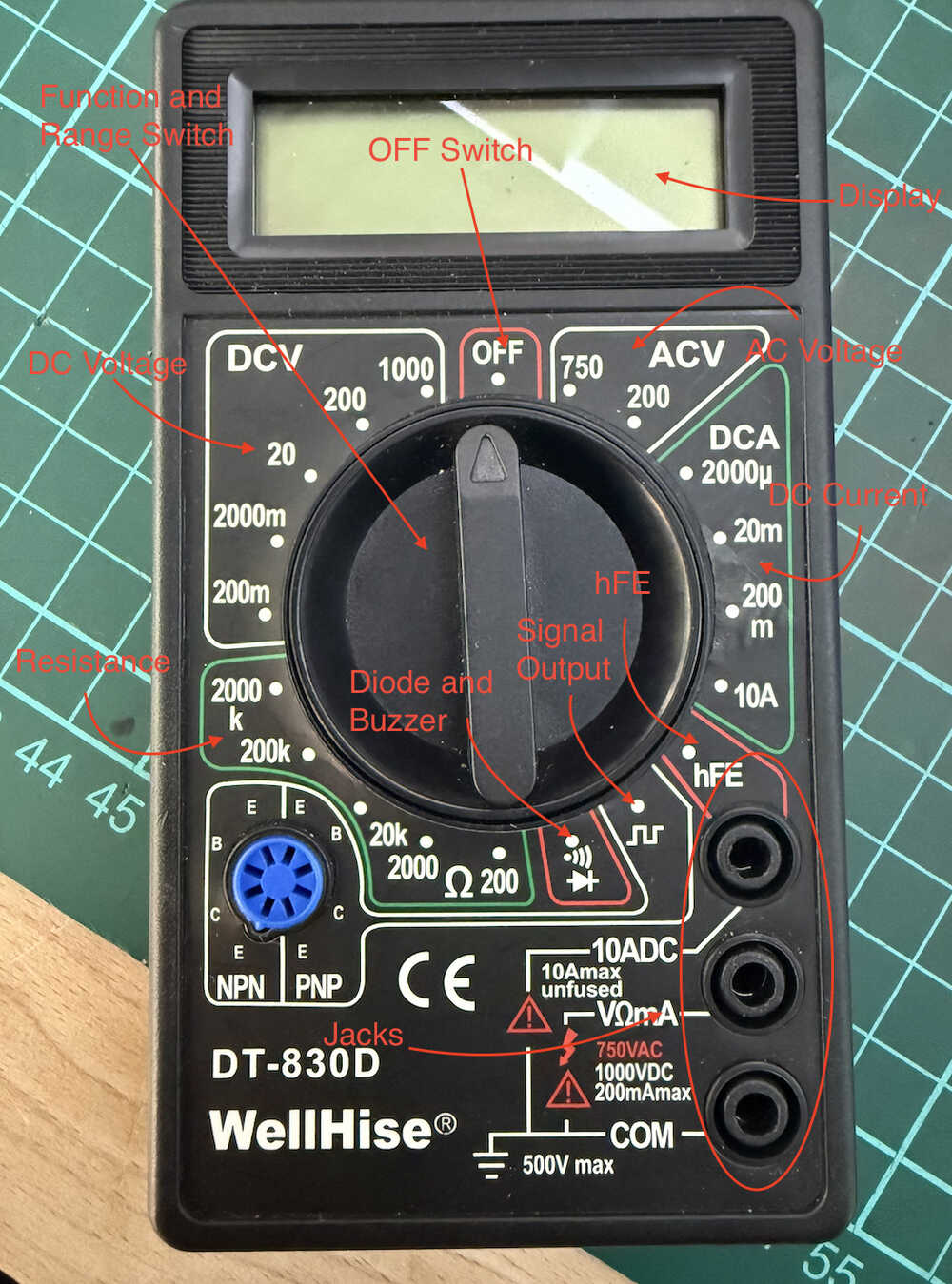
The bottom jack connects to the negative test lead (the black one). The middle jack connects to the positive test lead (the red one) for all voltage, resistance, and current measurements. The top jack is for the positive test lead (the red one) for current (between 200mA and 10A) measurement. There is no fuse for the 10A jack. To use safely, each measurement can not last for more than 10 seconds, and the interval between each measurement must be more than 15 minutes.
Square wave (50Hz) or sine wave (1000Hz) signal output. Level output: 5Vp-p
Vcc about 3V, Ib about 10µA, display hFE 1-1000.
Testing Voltage is about 2.8V, current is about 1mA. The approximate forward voltage drop in mV will be displayed. When the resistance is less than about 50 ohms, the buzzer will make a sound.
The Diode and Buzzer is especially important since we can see short circuits etc. after soldering our PCB or microcontroller.
There has to be 0V in the circuit. After that, touching the two leads to the two ends of the circuit will show how much resistance it has.
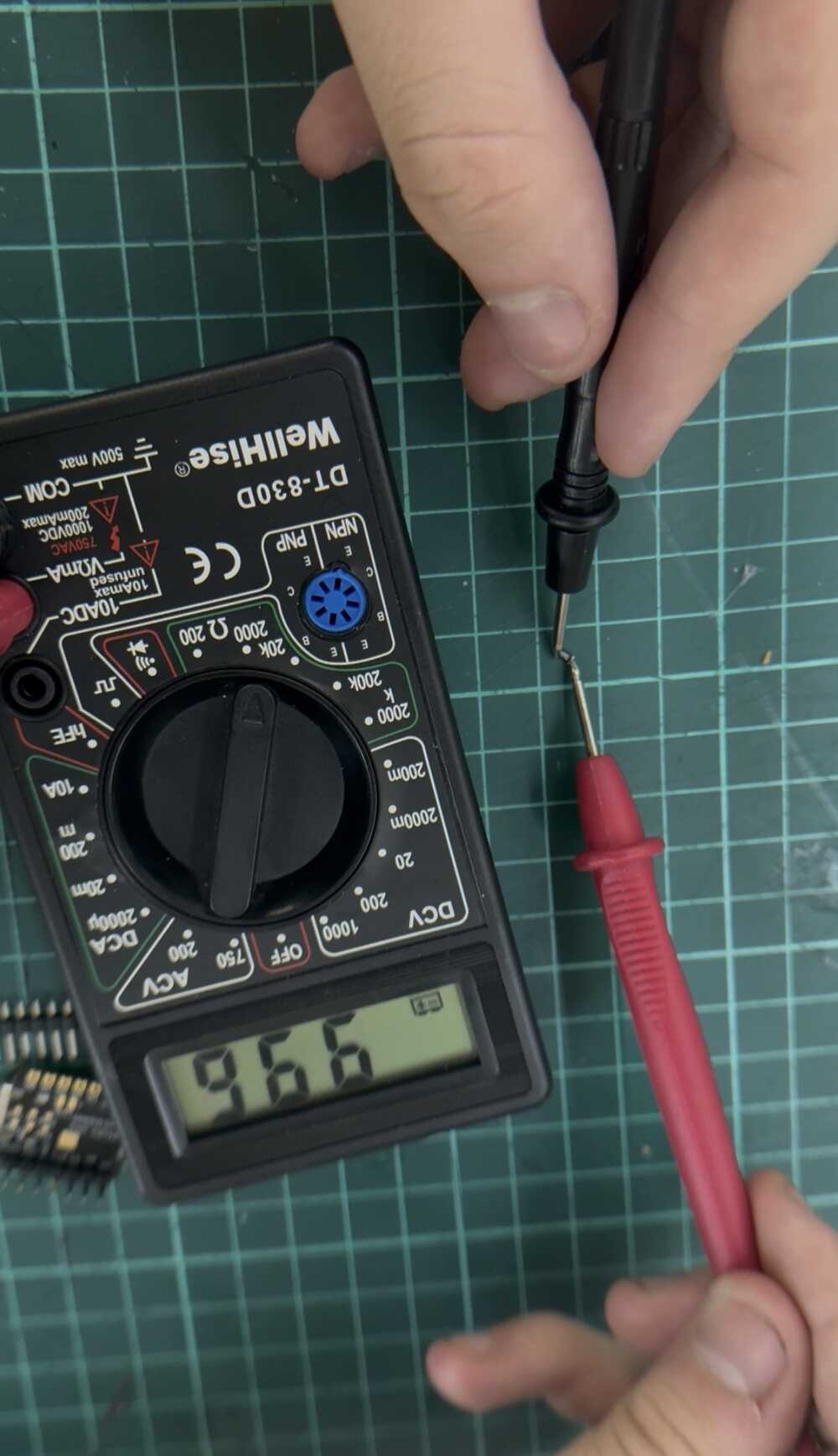
When you touch the two leads to the two ends of an active circuit, you'll be able to see its voltage.
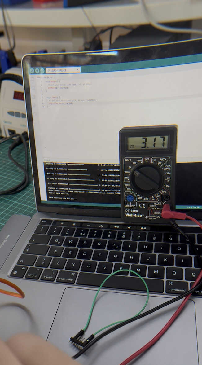
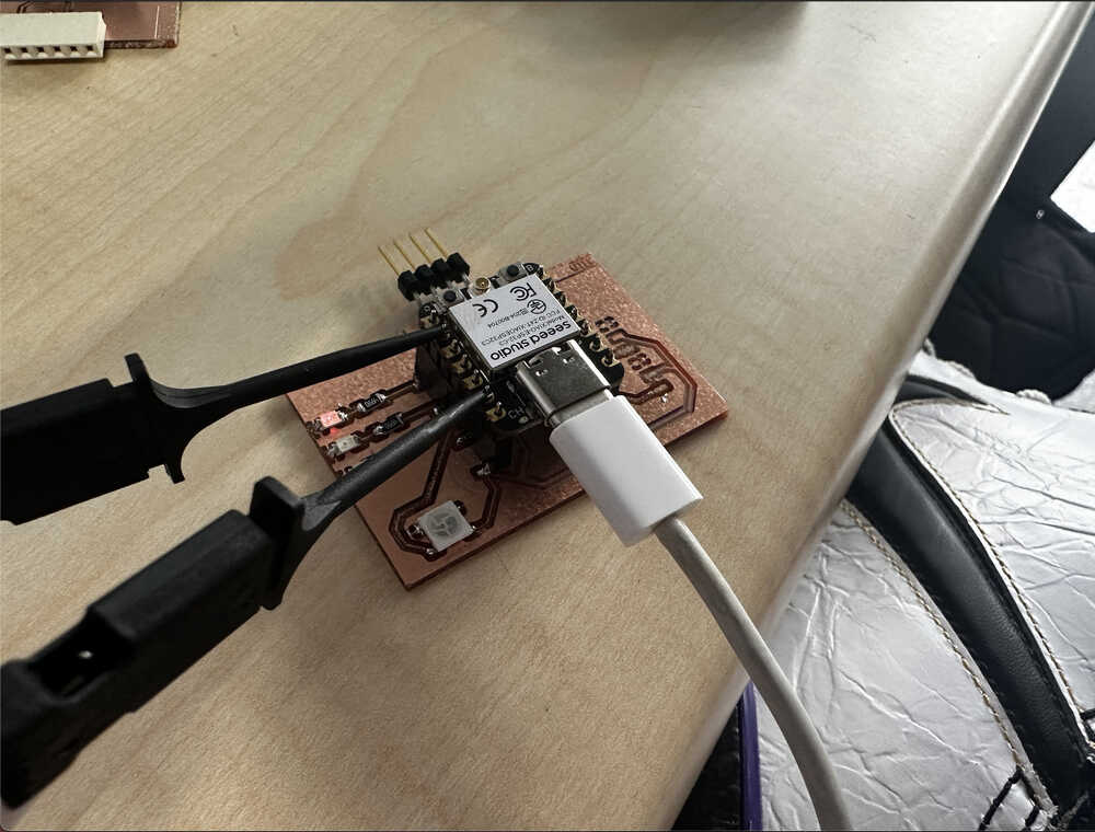
Here, I outputted some electricity from the D7 pin towards the GND (ground) pin.
An oscilloscope is a type of electronic test instrument that graphically displays varying voltages of one or more signals as a function of time. Their main purpose is capturing information on electrical signals for debugging, analysis, or characterization. The displayed waveform can then be analyzed for properties such as amplitude, frequency, rise time, time interval, distortion, and others.
Source: Wikipedia
Our group is using a Rigol DS1054Z oscilloscope.
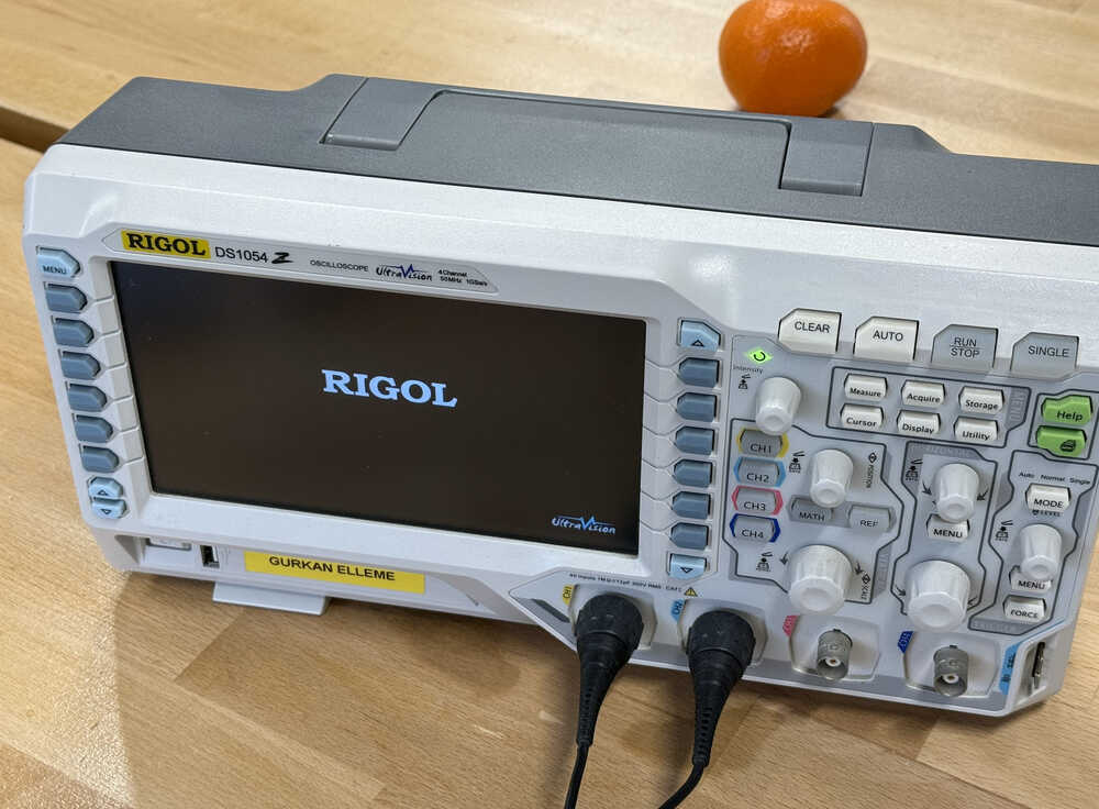
Oscilloscope: Link
Set Coupling to DC and Probe to 10X
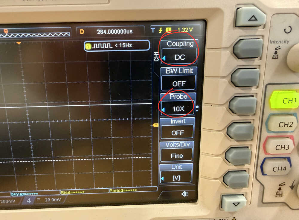
Connect the probe to the pin with voltage.
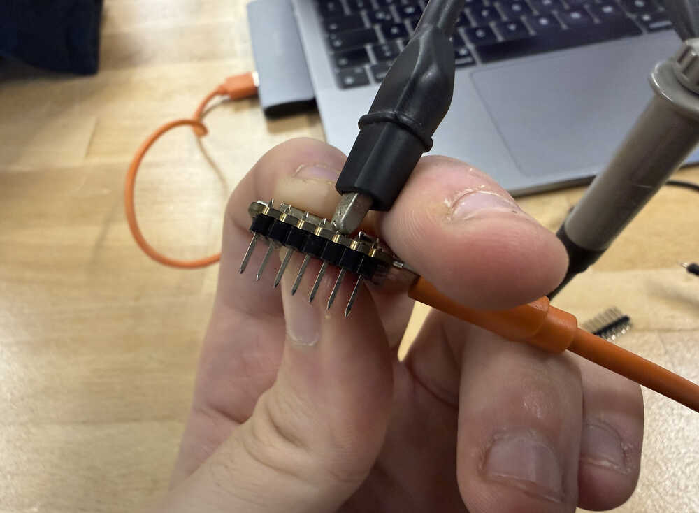
It can be an output pin or a 5V pin etc.
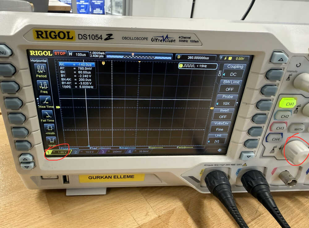
Set the circled value to 1V using the circled knob.
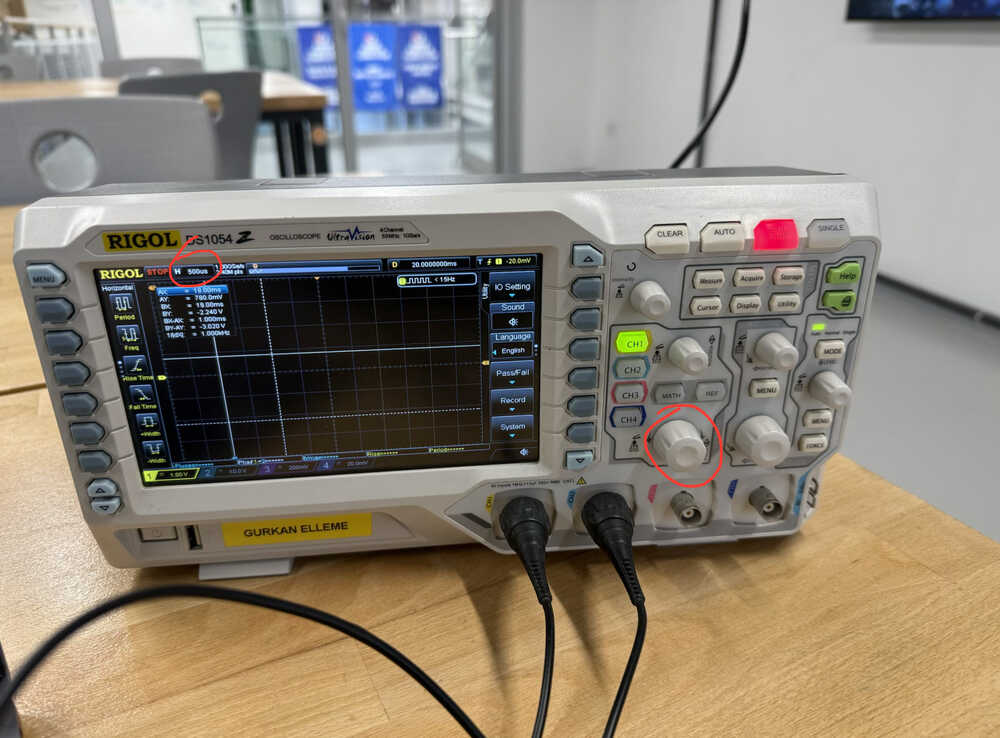
Set the circled value to 500us using the knob next to the circled one (I accidentally circled the wrong one).
After starting:
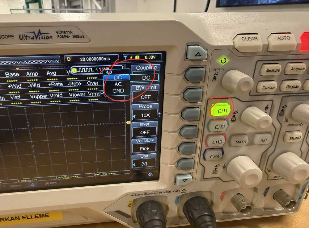
Set Coupling to AC.
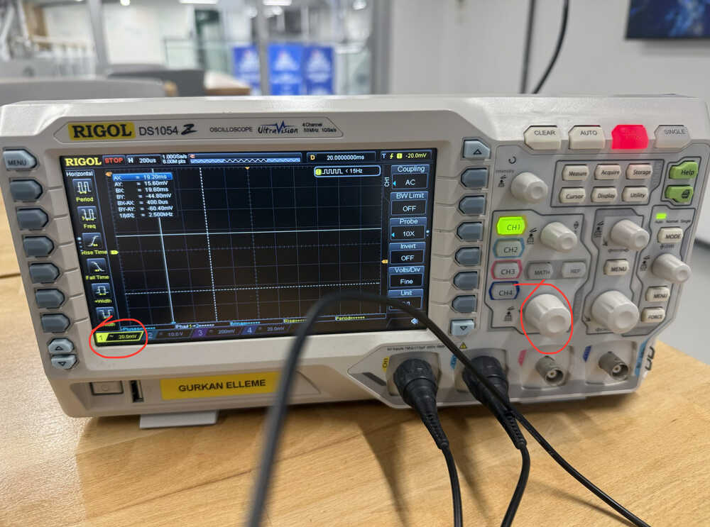
Using the circled knob, set the circled value to 20mV.
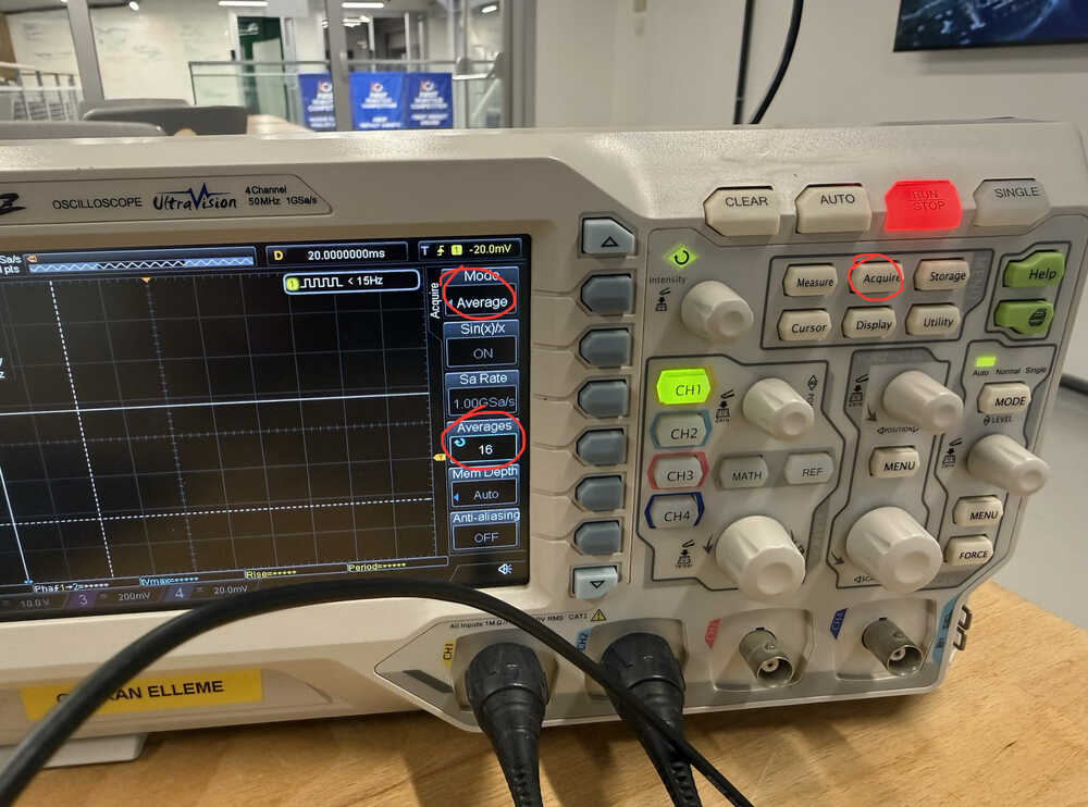
In the Acquire tab, set mode to Average, and set the Averages value to 16.
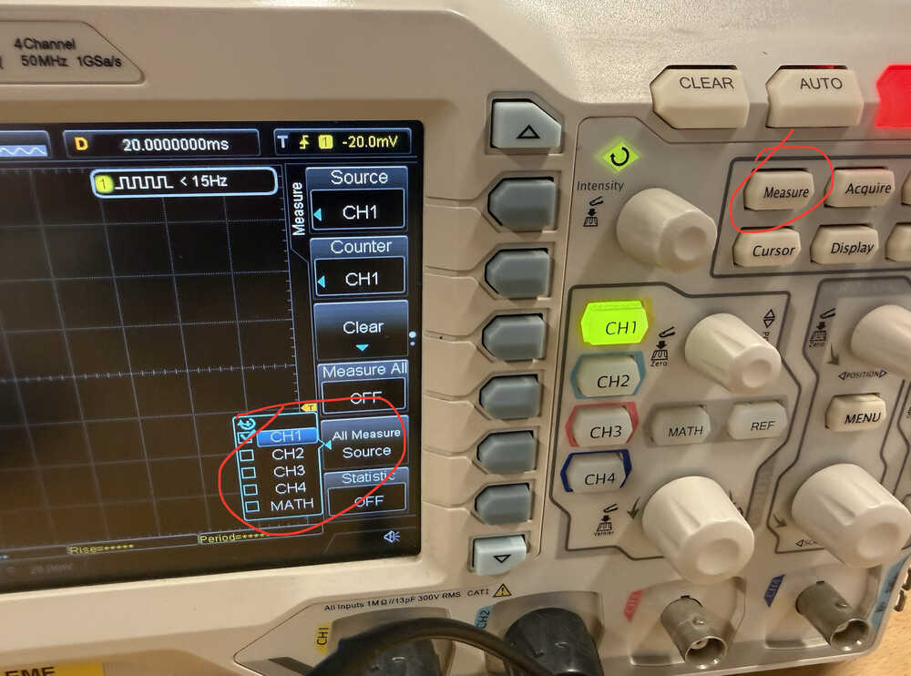
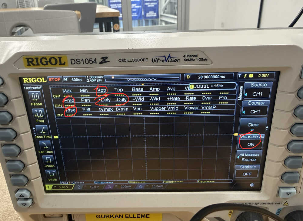
In the Measure tab, select CH1 for a measure source.
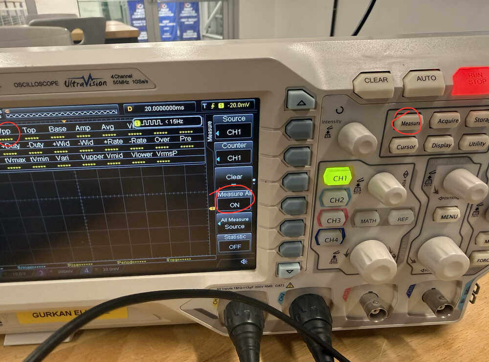
In the measure tab, set Measure All to ON.
The ripple:
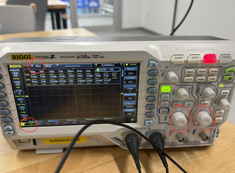
Set the circled values to 500us and 1V using the circled knobs.
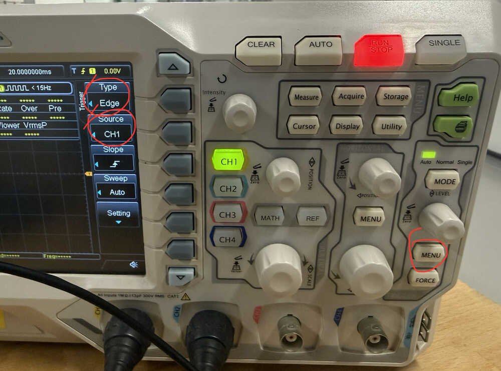
In the Trigger Menu, set the type to Edge and the source to CH1
Turn Measure All to ON in the measure tab.
Set the Coupling to DC.
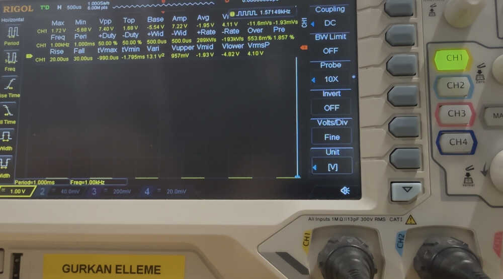
The values:
The ones at the top don't really come out because of lighting etc., but you can still see them if you look careful enough.
A power supply is an electrical device that supplies electric power to an electrical load. The main purpose of a power supply is to convert electric current from a source to the correct voltage, current, and frequency to power the load.
Source: Wikipedia
We'll be using a Profuse DPS305U power supply.
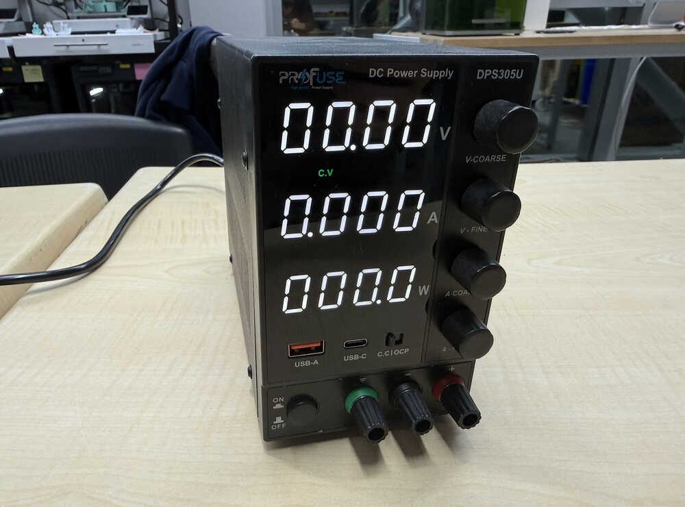
Power Supply: Link
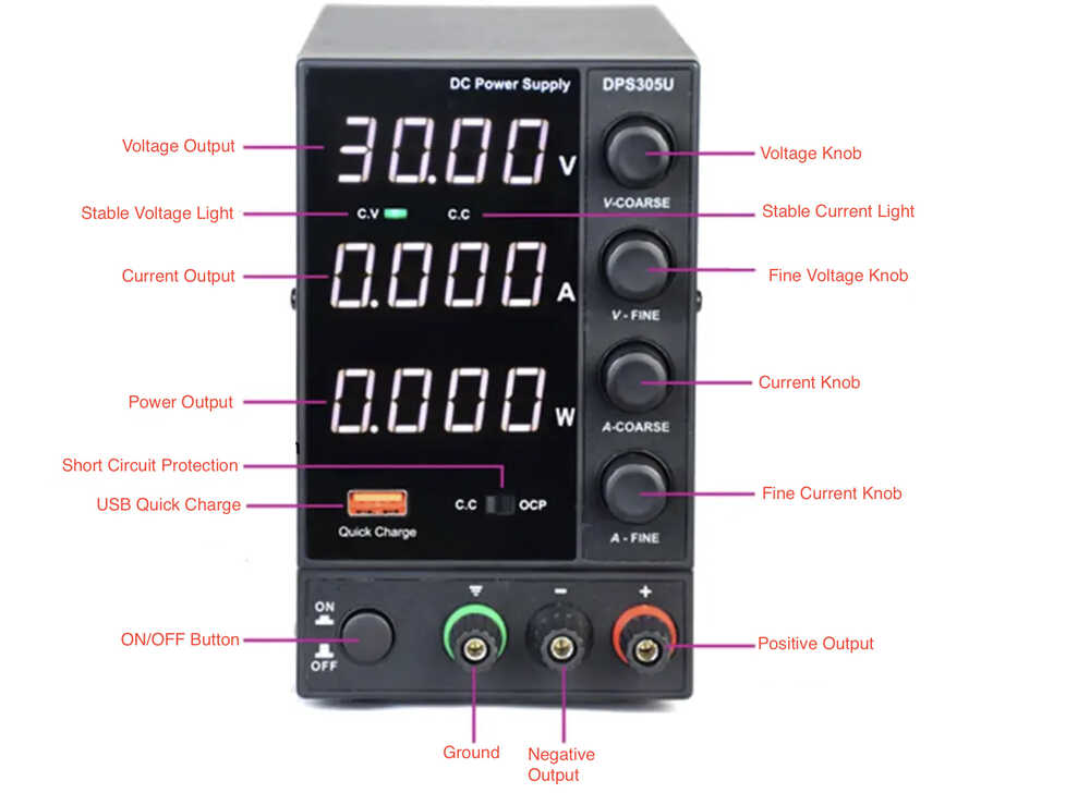
The power supply basically gives external power to support the operations of the microcontroller etc. If you're using something that requires higher voltage than 5V you must use an external power input from a power supply, battery etc.
Lighting an LED with 3V and 0.02A:
A logic analyzer is an electronic instrument that captures and displays multiple signals from a digital system or a digital circuit.
Source: Prodigy Technovations
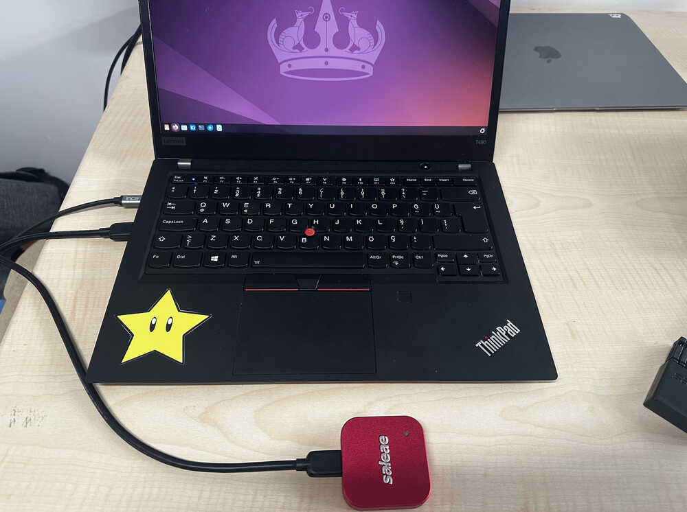
We used a Saleae logic analyzer to observe the behavior of a microcontroller.
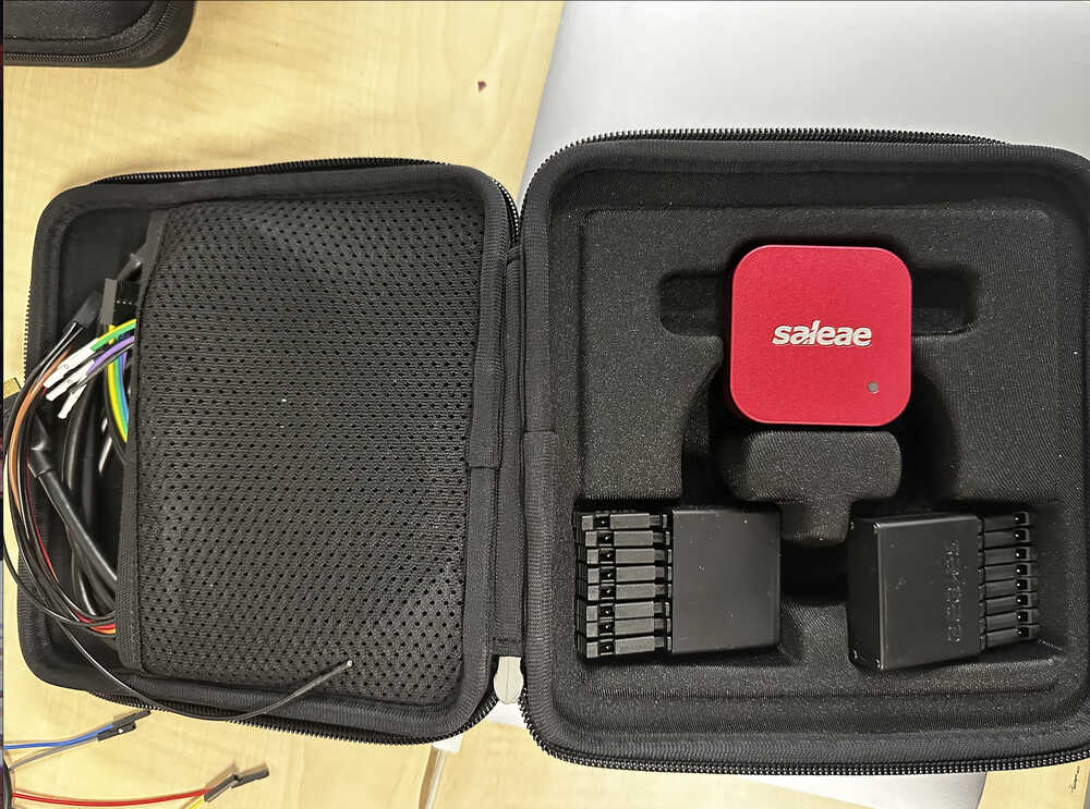
It looked like as below out of the box with it's connection cables, attachment pins and main module
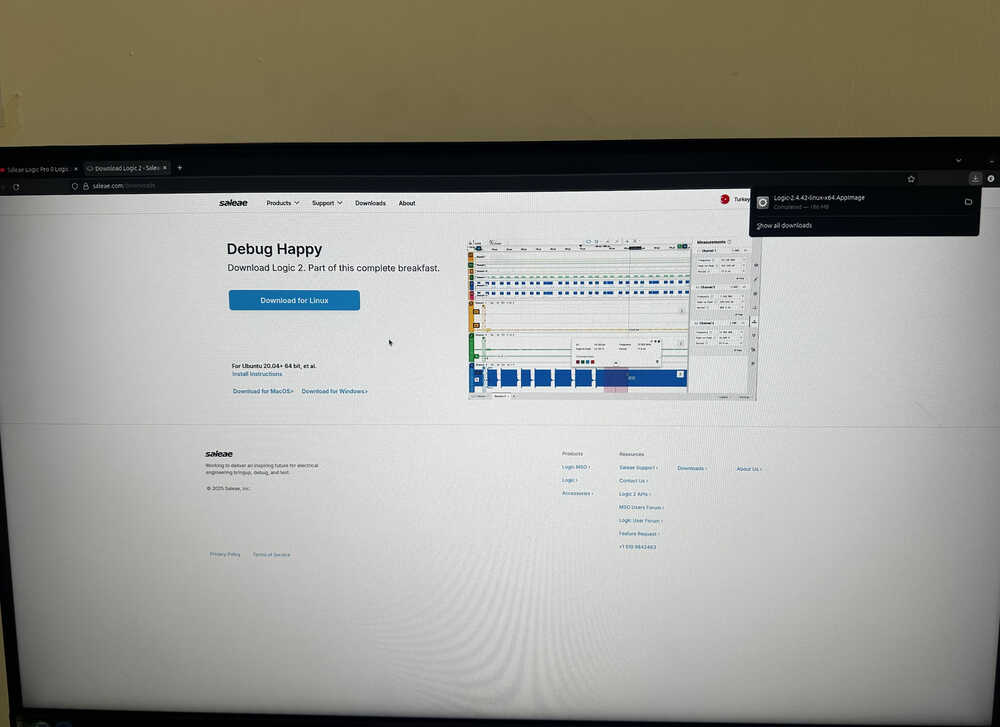
First we connected it to the computer, but had no light up realizing we needed the logic 2 software of the Saleae, so we installed it as below.
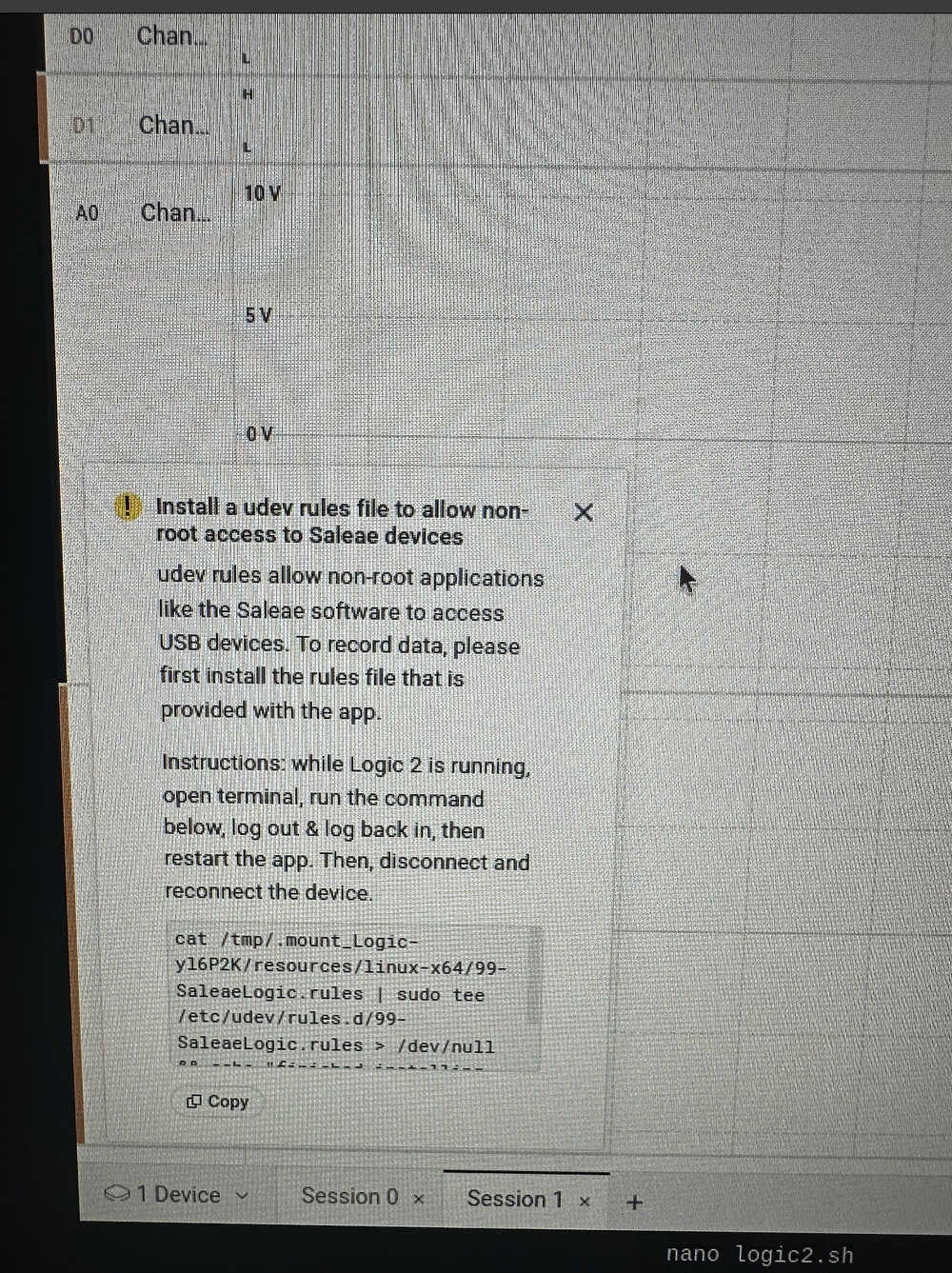
Lastly, before the connection was established, this warning popped up that the command there must be pasted to give room access to the Saleae device which I pasted and gave the device the necessary accesses for a full connection.
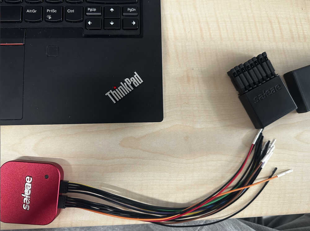
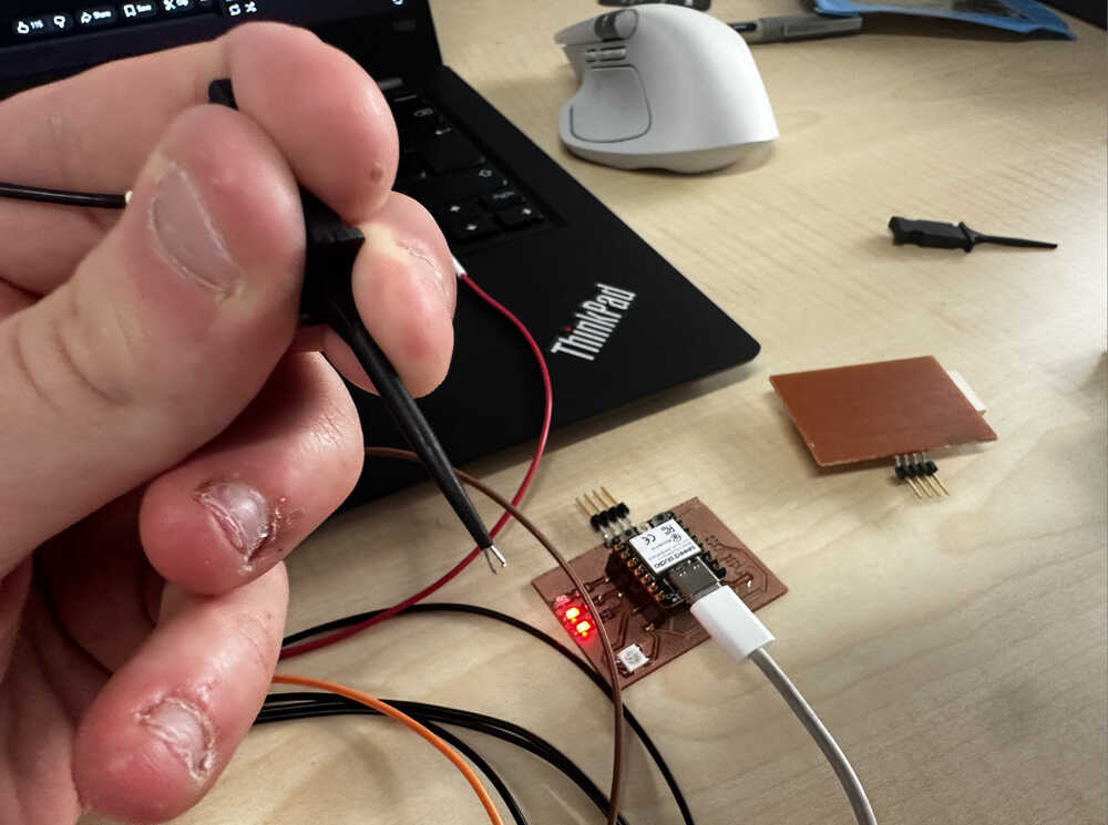
Next it was onto connecting the cables. I connected the cables to the given ports on the logic pro 8 to make proper connections with microcontroller device be established.
Next it was onto test one the power high/low detection test. First I discovered that when I pulled the moving part on the connection tips it popped out a small metal claw as below, that's what I used for the connection.
Then, I established the connection with the pins of one of the LED and the GND as below.
Next I ran the test as below.
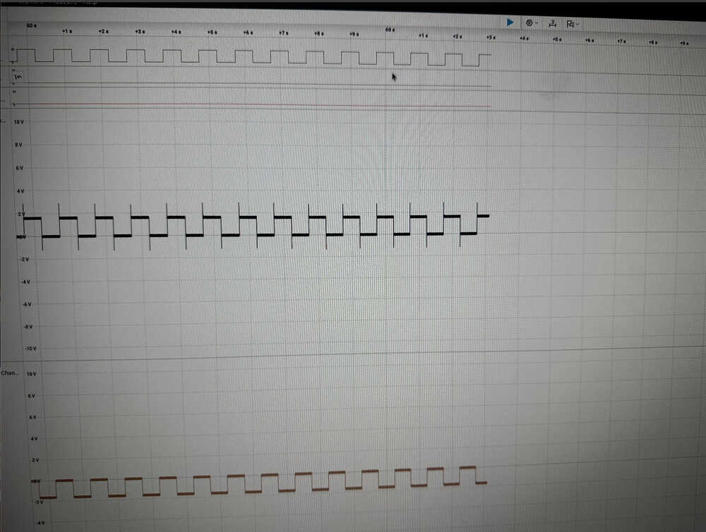
The high low going signals showed as below as the voltage on one analog pin rose the voltage on the other fell, which was interesting to see.
Next it was onto the i2c test. Though I though it would be smooth sailing it turned out to be quite the opposite. As can be seen from the video below though I was detecting out going signals from i2c pins it wasn't detecting an i2c device.
After debugging and trying every possible options I realized that the person who soldered the oled, which is also the person who is writing this, didn't solder it well enough causing the device being undetected.
After that the test went well and I detected the i2c processes using the logic analyzer as below.